

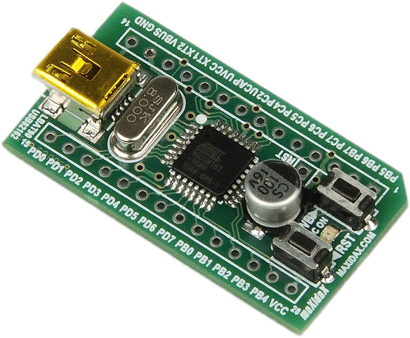
LBAT90USB162 Atmel® AT90USB162 Development Board
One of today's most widely used MCUs offering native USB support is the Atmel® AT90USB162. It provides an easy way to add USB functionality to any new design along with hundreds of different projects that are available. The LBAT90USB162 is an Atmel® AT90USB162 development board. This board is a cost-effective yet highly compatible, flexible and easy-to-use development tool, designed to give a quick start in developing code and for hardware prototyping and testing. It is clean in design and provides flexibility and convenience. The board has all the basic circuitry needed to work with the AT90USB162: USB connector and circuit, crystal, Reset and HWB buttons, power LED. The board offers flexible power: both 3.3 V and 5 V USB-powered or from external supply - please see Powering the Board or User's Manual or AT90USB162 datasheet. The board also features 100 mil headers, making it breadboard-friendly and easily connectable to any prototyping environment. Board design makes it compatible with other similar development boards featuring same or similar MCUs and virtually all design/development software and libraries. MCU comes pre-programmed with a bootloader allowing code to be programmed into the chip without any external programmer – simply by using the USB interface and the FLIP software from Atmel. To enter the bootloader mode, the RST button should be pressed and hold, then the HWB button pressed and hold, and then the RST button released. Any development board will probably see many versions of firmware. What if the bootloader gets destroyed cutting the way to reprogram the device via USB? Using external programmer connected via ISP or parallel is the only solution. Although this design doesn't have a dedicated ISP port, the ISP port of the MCU still can be used - simply disconnect any circuitry from lines PB1/SCLK, PB2/MOSI, PB3/MISO and use them together with the dedicated Reset (RST) header to reprogram the device (see LBAT90USB162 User's manual and AT90USB162 datasheet). This option isn't directly available with many other development boards. Hardware debugger like JTAGICE can also be used via the RST header. |
|||||||||||||||||||||||||||||||||||||
|
FEATURES
COMPATIBILITY As all MCU I/O pins are accessible and all MCU powering and clocking options are available the SBAT90USB162a is compatible with virtually every project and development tool designed for AT90USB162 and particularly for AVR MCUs. |
SPECIFICATIONS
|
||||||||||||||||||||||||||||||||||||
DOWNLOADS

|

|

|

|